
Flow Bench · Guide
The lip on a velocity stack, and what its radius is worth
A pipe end with no lip uses 57% of its own area. Put a 6 mm radius on it and the air uses 72% and 18% more gets through at the same pressure. Make it a full elliptical bellmouth and you gain a little more. Most of the prize is in the first few millimeters.
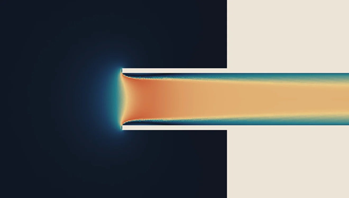
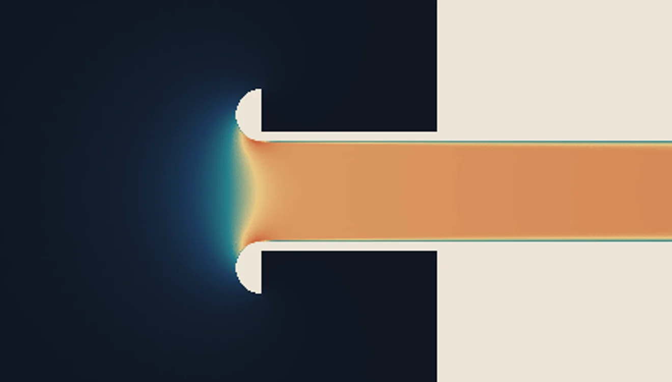
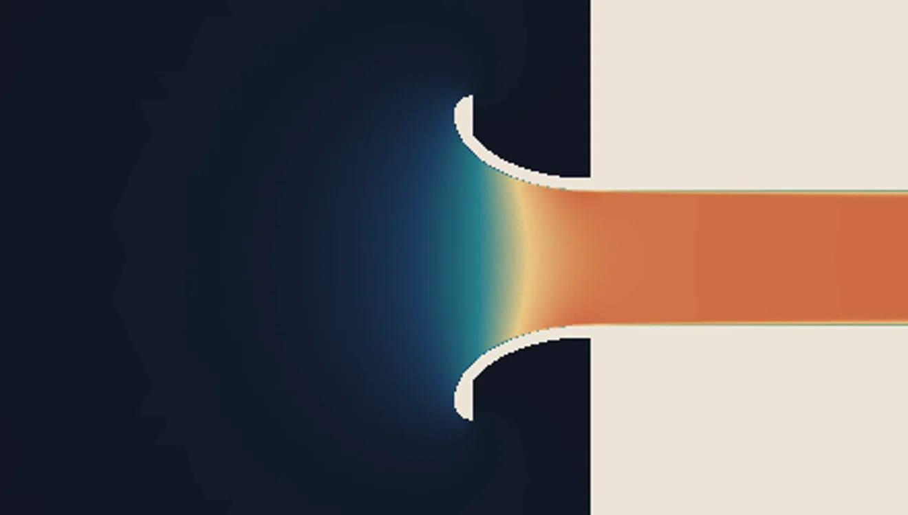
Three of Flow Bench's own runs on the same 23 mm pipe, drawing from still air at a pressure ratio of 1.04. Color is the air's speed, scaled to each run's own fastest air; the streaks follow each run's air, with the fast air slowed so the drift outside can be seen.
Why
What a sharp edge does to the air
Air heading into a pipe comes from every side, including from behind the mouth. At a square-cut end the air arriving along the outside of the pipe has to turn back on itself to get in. It cannot turn that sharply, so it leaves the wall at the corner and the flow narrows to a jet just inside the mouth, the vena contracta. The pipe is 23 mm across, but for a short way the air is using a hole of about 17 mm.
The flow coefficient here is that fraction: the jet's area at its narrowest over the pipe's area. A radius gives the air a wall it can follow around the turn, so the jet stays nearly as wide as the pipe.
The numbers
Three mouths on the same pipe
| Mouth | Flow coefficient | Air | Against no lip | Published |
|---|---|---|---|---|
| Plain pipe, no lipA square-cut pipe end | 0.57 | 30.4 g/s | the baseline | 0.57, 30.0 g/s |
| Simple radiusA 6 mm radius, mouth 35 mm across | 0.72 | 35.9 g/s | 18% more air | 0.72, 34.8 g/s |
| Elliptical bellmouthAn elliptical profile 23 mm long, mouth 49 mm across | 0.75 | 36.6 g/s | 20% more air | 0.74, 36.1 g/s |
- The first three columns are Flow Bench's full 3D runs. The last is Blair and Cahoon's, from Race Engine Technology: their figures are computed with a commercial flow solver, which the article shows agreeing closely with rig measurements for the first two mouths.
- The two sets agree on the coefficient within about 1%. They differ more on the air itself, by up to 3%. The coefficient is worked out from the air and from a pressure read in the pipe; the article does not say where it read that pressure, and Flow Bench reads it 105 mm past the pipe's face.
- Their own summary of the same step: a simple radius is worth 27% on the coefficient and 16% on the air, and the best shape they found adds about 4% to the coefficient beyond that.
If you are drawing one
What the published study recommends
Blair and Cahoon ran a wide range of radiused, aerofoil and elliptical mouths. Their design advice comes down to four things:
- An elliptical profile. It came out slightly ahead of the aerofoil one.
- About as long as the pipe is wide. They call the winning proportions “short and fat”.
- A mouth about 2.13 times the pipe's diameter. On a 23 mm pipe, 49 mm, which is the third run above.
- A corner radius on the outer edge of 0.08 times the mouth's diameter, so the air arriving from behind has something to turn around as well.
They also conclude that rectangular intake ducts and mouths should be avoided where the design allows, and that the whole subject matters less than its reputation suggests, except where the last few horsepower in a hundred decide a race.
Before you rely on it
What these runs do not cover
- One pressure. Everything here is at a pressure ratio of 1.04. The coefficient rises with pressure ratio for every mouth: in a full 3D sweep the simple radius went from 0.72 at 1.04 to 0.78 at 1.20, within 0.6% of the published curve at each of six pressures. The other two mouths have been run in 3D at 1.04 only.
- Steady air. A running engine draws in pulses. A steady run says how well a mouth flows, not what the engine does with it.
- Open air, one stack. No airbox wall, no filter, no neighbor.
- No measurement of our own yet. The comparison is with published figures. A flow bench and a dyno are where that comes from.
- Power. More air through the mouth is not the same as more power: the length of the intake decides where in the rev range the engine can use it. The guide to what a flow number means for horsepower has why.
For racing use only.
FAQ
The lip, answered
Short answers, with the numbers above behind them.
Does a velocity stack need a radius on its lip?
Yes. A square-cut pipe end is the worst mouth there is: the air cannot turn the sharp corner, so it pulls away from the wall and the pipe flows as if it were smaller. In Flow Bench’s runs a 6 mm radius on a 23 mm pipe passed 18% more air at the same pressure.
How big should the radius be?
Big enough that the air stays on the wall, and after that the gain is small. Going from no lip to a 6 mm radius raised the flow coefficient from 0.57 to 0.72. Going from that radius to a full elliptical bellmouth with a mouth 49 mm across raised it to 0.75.
What is the best shape for a bellmouth?
Blair and Cahoon’s published study found an elliptical profile slightly ahead of an aerofoil one, with the bellmouth about as long as the pipe is wide, the mouth about 2.13 times the pipe’s diameter, and a corner radius on the outer edge of 0.08 times the mouth’s diameter. They put its advantage over the simplest bellmouth at about 3.5%.
Is a longer velocity stack better?
Length does a different job. The lip decides how much of the pipe the air uses. The length of the whole intake decides at which engine speeds the pressure wave helps. The stack length calculator covers that.
Do these numbers apply inside an airbox?
Not directly. These runs draw from open, still air through one stack. In an airbox the walls, the filter and the neighboring stacks change how air reaches each mouth, and Flow Bench’s airbox runs show that for each stack. On a running engine the air also arrives in pulses, which a steady run does not show.
Flow Bench
Run your own stack
Flow Bench runs the stack you draw, beside the one you have. It is in open beta: free to use, and you pay only for the runs you start. Leave an address for a short note when it adds a new kind of part.
A message is on its way with a link in it. Open that link and you are on the list. Nothing else gets sent until you do.
That did not come through with an email address in it. Try once more.
That is several signups from one connection in a row. Wait a minute and try again.

Follow along
Follow the trip
We'll post photos, video, and the next morning's plan as we go.